What Are Hydraulic Power Units and How Do They Work?A hydraulic system employs enclosed fluid to transfer energy from one source to another, and subsequently create rotary motion, linear motion, or force. The power unit/pack provide the power needed for this transfer of fluid. Unlike standard pumps, hydraulic power units use multistage pressurization networks to move fluid, and they often ...
Detailed Diagram Of A Secondary Cone CrushersHome Detailed Diagram Of A Secondary Cone Crushers PEW series Jaw crusher features big crushing ratio, reliable operation, easy maintenance and low operating cost. It is the.
Aircraft Hydraulic System ValvesHydraulic system pressure can be routed with the selector valve to operate the unit in either direction and a corresponding return path for the fluid to the reservoir is provided. Figure 1. Operation of a closedcenter fourway selector valve, which controls an actuator. There are two main types of selector valves: opencenter and closedcenter ...
Hydraulic and Plumbing Symbols Category – Free CAD Blocks . · Valve Flow Control Spring Return Roller Plunger Operated. March 19, 2020. Valve flow control spring return roller plunger operated hydraulic symbols. A free AutoCAD DWG file download. Hydraulic symbol blocks to Australian Standard, Graphic Symbols for General Engineering Part 1: Hydraulic and Pneumatic Systems. ..
® Valves · Hydraulic 3PC Directional Control Valve · 3PC Valves. Closedcenter and loadsensing features improve fuel efficiency. Available integrated ride control. Priority control of functions is offered. Proportional flow is shared among sections. Five spool configurations are available. Internal antidrift valves and pilot supply eliminate external lines. Inlet manifold options support ...
Elevator and Escalator Online Tools and DownloadsKONE Elevator Planner Plan elevator configurations and shaft dimensions for your project. Download customized CAD and BIM files and equipment specifiions for your elevator. Elevator Car Designer Design your own elevator car interior for KONE MonoSpace 500, KONE MonoSpace 700 or KONE MiniSpace. Escalator Tools Escalator Planner
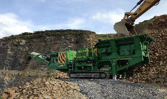
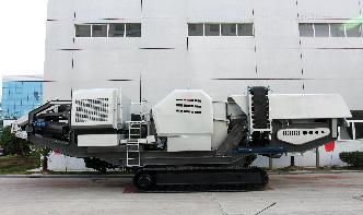
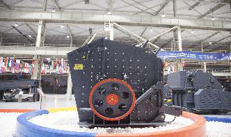
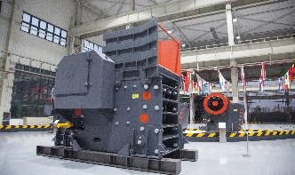
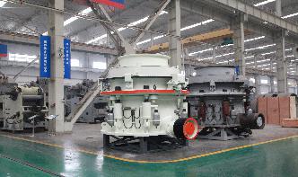
® HP100™ cone crusherLess downtime, more confidence. HP100™ cone crusher delivers less downtime and increased operator confidence. Dualacting hydraulic tramprelease cylinders are used to let the crusher pass tramp iron and to provide a large clearing stroke if needed. The double accumulator combination provides better reactivity of the hydraulic system.
line diagram crusher coneelectric diagram for crusher in cement factory. Dec 05, 2021 0183 32 Diagrams crusher in the cement factory bbmi mls3726 vrm schematic diagram of ballmill crusher mills, cone, arrow g Line diagram of crusherfrom india may 16 2013 cone crusher diagram cone crushing machine capacity cone crusher electric diagram for crusher in cement factory electrical schematic ....
| is the world's leading provider of onroad load handling equipment, intelligent services, smart and connected solutions.
mineral cone crusher hydraulic daigram · high pressure cone crusher hydraulic diagram. high pressure cone crusher hydraulic diagram. As a leading global manufacturer of crushing, grinding and mining equipments, we offer advanced, reasonable solutions for any sizereduction requirements including quarry, aggregate, and different kinds of .
Unconfined Compression Test | A typical stressstrain diagram deriving from a Uniaxial Compression Test of an undisturbed specimen of basalt is presented in Figure 1. The UCS is the peak value of the diagram and is equal to MPa. Photos of the specimen before and after the test are presented in Figure 2.
How to Detect and Repair a Faulty Hydraulic Lifter · The most obvious symptom of a faulty hydraulic lifter is the noise it creates in your car's engine. You can usually distinguish the faulty lifter by the distinct sound. Instead of a knock or ping, a faulty hydraulic lifter will usually make a sound more reminiscent of a tapping sound. The tapping will be quick in rhythm and may occur when the ...
The Brinell test procedure – Brinel hardness testThis results in different forcediameter indexes (also referred to as loading levels or load factors) within the Brinell method, whereby the quotient of test force and square of the ball diameter is kept constant: B = *F/D 2. The five common forcediameter indexes are 1,, 5, 10 and 30.
JCB FiltersJCB transmission filters have specifically designed end plates and crimping to deal with high pressure spikes encountered in transmission hydraulic circuits. The filter bypass valves are accurately set preventing premature valve opening and contamination of the system. Be aware that nongenuine filters do not conform to these design requirements.
diagram of a cone crusher4 1/4 Cone Crusher Parts Diagram 4 1/4 cone crusher parts diagram. if you want to get more detailed product information and prices, crynchy recommend that you get in touch with us wiring diagrams for hydraulic cone crushers
4,032 Erection Vector Images, Erection Illustrations⬇ Download vector images of Erection on Depositphotos Vector stock with millions of royaltyfree illustrations at affordable prices.
Types of Prestressing Systems and Anchorages in Prestressed .The diameter of the bar is between 12 and 28mm. bars provided with threads at the ends are inserted in the performed ducts. After stretching the bars to the required length, they are tightened using nuts against bearing plates provided at the end sections of the member (). : End Anchorage for Lee McCall System 5.
schematic diagram of cone crusherSBM mobile cone crusher hydraulic system diagram. cone crusher for sale, used crushers for sale | SBM Crusher, wiring diagram power pack pada, at the heart of the maxtrak is the automax cone crusher with hydraulic. Read More.
Block Diagram Of Hydraulic Cone CrusherBlock diagram of hydrsulic cone crusher. block diagram of the primary crusher,Hydraulic Cone Crusher Control Wiring Diagram Block diagram of hydrsulic cone crusher block diagram of hydrsulic cone crusher cone crushers 911 metallurgist apr 17 2018 hydrocone crusher is the hydraulic support from which its name is derived and on the left is .
How to Identify the Correct Hydraulic Hose Fittings · 30 degree flare (BSPP) ORing Face Seal (ORFS) 60 degree NPSM Swivel. 60 degree Cone (BSPP) 60 degree Cone (Metric) To determine the type you're actually working with, there's a simple fourstep process involved. First of all, you need to figure out whether it's a permanent or reusable type, and the permanent fittings will be those which ...
Hydraulics, rear selective control valves (SCVs) · The position of the one SCV valve that comes in base equipment for 6030 and 7030 Standard Tractors is in position 1, closest to the hydraulic block on the lefthand size. The more SCVs that are ordered or added change the position of the SCV valves. The SCV positions read from left to right. The maximum number of rearmounted SCVs is four.